A simplest program to test the RTOS for the little core
Print a log every 1 second. After the big core Linux starts, you can observe the continuous log printing of the test program. It will end and exit after 60 times(1 minute).
diff --git a/freertos/cvitek/task/comm/src/riscv64/comm_main.c b/freertos/cvitek/task/comm/src/riscv64/comm_main.c
index a3dfd862f..634cc65b7 100644
--- a/freertos/cvitek/task/comm/src/riscv64/comm_main.c
+++ b/freertos/cvitek/task/comm/src/riscv64/comm_main.c
@@ -58,11 +58,17 @@ DEFINE_CVI_SPINLOCK(mailbox_lock, SPIN_MBOX);
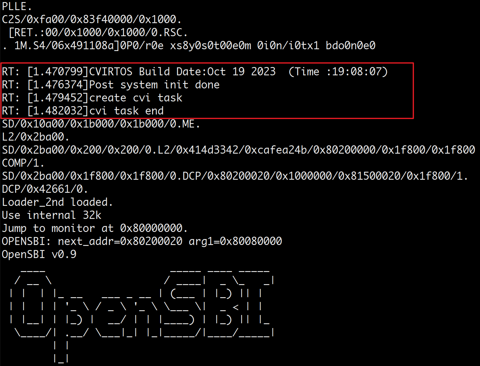
void main_cvirtos(void)
{
+ int i = 0;
printf("create cvi task\n");
/* Start the tasks and timer running. */
+ for (i = 0; i < 60; i++) {
+ printf("i ===> %d\n", i);
+ mdelay(1000);
+ }
+
/* If all is well, the scheduler will now be running, and the following
line will never be reached. If the following line does execute, then
After making the modifications, you need to recompile the firmware.
Not elegant, but blink the on-board LED 5 times at start-up using the little core on FreeRTOS:
  // GPIOC24 is the blue LED.
  // The datasheet page 536 says:
  // Configure register GPIO_SWPORTA_DDR and set GPIO as input or output.
  // When the output pin is configured, write the output value to the
  // GPIO_SWPORTA_DR register to control the GPIO output level.

  #define GPIO2 0x03022000
  #define GPIO_SWPORTA_DR 0x000
  #define GPIO_SWPORTA_DDR 0x004

  *(uint32_t*)(GPIO2|GPIO_SWPORTA_DDR) = 1 << 24;
  for (i = 0; i < 5; i++)
  {
    *(uint32_t*)(GPIO2|GPIO_SWPORTA_DR) = 1 << 24;
    mdelay(100);
    *(uint32_t*)(GPIO2|GPIO_SWPORTA_DR) = 0;
    mdelay(100);
  }