Thank you! Yes, I had found both files, but was not clear that SPINOR_MISO, etc… actually directly translated to SPI2_MISO (or SPI2_DI). I know it’s not enabled by default - so what is needed to enable by default, just changes to line 230 in duo-buildroot-sdk/u-boot-2021.10/board/cvitek/cv180x/board.c
pinmux_config(PINMUX_SPI2);
So there is no need to make further changes to build/boards/cv180x/cv1800b_milkv_duo_sd/dts_riscv/cv1800b_milkv_duo_sd.dts?
Also, Enable SPI2 and the corresponding spidev on Milk-V Duo shows adding cs-gpios = <&porta 18 0>; to do dts – is that necessary?
What about the modification to cvitek_cv1800b_sophpi_duo_sd_defconfig shown in that post?
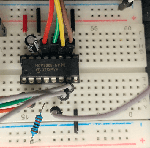
Here is my setup - the same setup that works without issue through /dev/spidev0.0 on Pi, etc…
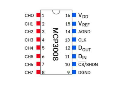
The MCP3008 chip:

The chip configuration on breadboard:
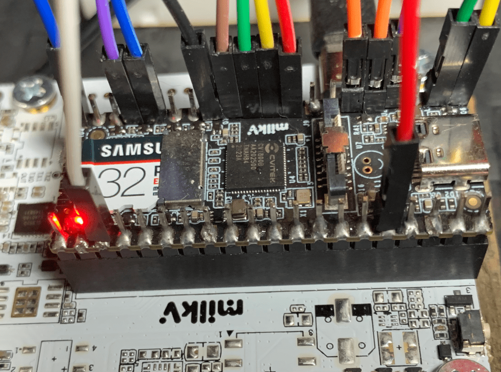
Connection on GP6 - GP9 on the Milkv-Duo:
The problem is when read through /dev/spidev0.0 there are nothing but stray voltages on various channels:
# mcp3008spi "/dev/spidev0.0" 100
opened SPI device: /dev/spidev0.0 on file descriptor: 3
  mode    : 0
  bits    : 8
  clock   : 1350000
  delay   : 5
  samples : 100  (~20 seconds)

all channel output:

  chan[0] :  0.00
  chan[1] :  0.41
  chan[2] :  0.00
  chan[3] :  0.00
  chan[4] :  0.83
  chan[5] :  0.41
  chan[6] :  0.00
  chan[7] :  0.00
Where the voltages should be:
  chan[0] :  1.69
  chan[1] :  2.71
  chan[2] :  1.36
  chan[3] :  3.29
  chan[4] :  0.00
  chan[5] :  0.00
  chan[6] :  0.00
  chan[7] :  0.00
As shown by the ADS1115 ADC chip on II2C (same voltages going to the MCP3008 chip channels 0-3 just in different order) shown below:
# ads1115

ADS1115 each input channel (AINx) configured for
single-shot, 4.096V gain, 128 SPS

  Outputting 100 analog input samples at 5Hz  (~20 sec)

  channel, reg-values and voltages:

  channel[0] : 0x66d6  (3.29 V)
  channel[1] : 0x34b8  (1.69 V)
  channel[2] : 0x54b8  (2.71 V)
  channel[3] : 0x2a5c  (1.36 V)
So if everything is provided in the buildrood-sdk for SPI2 on /dev/spidev0.0 why is nothing working?
It just seems that there should be a /dev/spidev2.0 (bus 2 channel 0). Or do I just not understand how the Duo is configured?
For completeness, I’ll post the code as well:
#include <stdint.h>
#include <unistd.h>
#include <stdio.h>
#include <stdlib.h>
#include <fcntl.h>
#include <sys/ioctl.h>
#include <linux/types.h>
#include <linux/spi/spidev.h>

typedef struct {          /* SPI device struct for mcp3008 */
  struct spi_ioc_transfer spi_xfer;
  uint8_t buf[6];
  int fd;
  uint8_t mode,
          cepin;
} spidev;

/* SPI and mcp3008 constants  */
#define SPIDEVFS      "/dev/spidev0.0"
#define BITS          8
#define CLOCK         1350000
#define DELAY         5

#ifdef MILKVFS
/* 3rd attempt with GPIOXX numbers - failed same vals as 2nd attempt
#define SPI_CLK      23
#define SPI_MOSI     22
#define SPI_MISO     21
#define SPI_CE       18
*/
/* 2nd attempt - very low voltage readings on wrong pins
 * next try enabling spidev2 in cv1800b_milkv_duo_sd.dts?
 */
#define SPI_CLK       6
#define SPI_MOSI      7
#define SPI_MISO      8
#define SPI_CE        9

/* 1st attempt through /dev/spidev0.0 - failed - no readings at all
#define SPI_CE       17
#define SPI_MISO     16
#define SPI_MOSI     19
#define SPI_CLK      18
*/
#else
#define SPI_CE        8
#define SPI_MISO      9
#define SPI_MOSI     10
#define SPI_CLK      11
#endif

/**
 * @brief initialize the SPI system (e.g. open "/dev/spidev0.0") and configure
 * the device struct for reading from the mcp3008.
 * @param spidevfs filesystem device node for SPI.
 * @param dev pointer to struct holding mcp3008 configuration.
 * @param delay microsecond delay for mcp3008 conversion (sample switching).
 * @param clock SPI bus speed in Hz.
 * @param bits bits per-bytes (e.g. CHAR_BITS).
 * @param mode SPI_MODE_x (single-ended or pseudo-differential pairs).
 * @param cepin CS/CE GPIO pin number.
 * @return returns 0 on success, -1 otherwise.
 */
int spi_device_init (const char *spidevfs, spidev *dev, uint16_t delay,
                      uint32_t clock, uint8_t bits, uint8_t mode, uint8_t cepin)
{
  /* initialize struct members */
  dev->spi_xfer.tx_buf = (unsigned long)dev->buf;
  dev->spi_xfer.rx_buf = (unsigned long)(dev->buf + 3);
  dev->spi_xfer.len = 3;
  dev->spi_xfer.delay_usecs = delay;
  dev->spi_xfer.speed_hz = clock;
  dev->spi_xfer.bits_per_word = bits;

  dev->mode = mode;
  dev->cepin = cepin;

  /* open spi device in Linux sysfs */
  if ((dev->fd = open (spidevfs, O_RDWR)) == -1) {
    perror ("open spidevfs");
    return -1;
  }
  /* set device mode */
  if (ioctl (dev->fd, SPI_IOC_WR_MODE, &dev->mode) == -1) {
    perror ("error init SPI_IOC_WR_MODE");
    return -1;
  }
  /* set number of bits per word (byte) */
  if (ioctl (dev->fd, SPI_IOC_WR_BITS_PER_WORD,
            &dev->spi_xfer.bits_per_word) == -1) {
    perror ("error init SPI_IOC_WR_BITS_PER_WORD");
    return -1;
  }
  /* send requested SPI bus speed */
  if (ioctl (dev->fd, SPI_IOC_WR_MAX_SPEED_HZ,
            &dev->spi_xfer.speed_hz) == -1) {
    perror ("error init SPI_IOC_WR_MAX_SPEED_HZ");
    return -1;
  }
  /* read configured SPI bus speed */
  if (ioctl (dev->fd, SPI_IOC_RD_MAX_SPEED_HZ,
            &dev->spi_xfer.speed_hz) == -1) {
    perror ("error init SPI_IOC_RD_MAX_SPEED_HZ");
    return -1;
  }

  return 0;
}


/**
 * @brief set channel to psuedo-differential compare mode.
 * @param channel channel to set control bits on (SGL/DIF = 0, D2=D1=D0=0).
 * @return returns control bits set for channel.
 */
uint8_t channel_cfg_differential (uint8_t channel)
{
  return (channel & 7) << 4;
}


/**
 * @brief set channel to single-ended input mode.
 * @param channel channel to set control bits on (SGL/DIF = 1, D2=D1=D0=0).
 * @return returns control bits set for channel.
 */
uint8_t channel_cfg_single (uint8_t channel)
{
  return (0x8 | channel) << 4;
}


/**
 * @brief read sample from mcp3008 for channel.
 * @param dev pointer to mcp3008 device struct.
 * @param channel analog input channel to read.
 * @return returns raw 10-bit value for sample.
 */
int spi_read_adc (spidev *dev, uint8_t channel)
{
  dev->buf[0] = 1;
  dev->buf[1] = channel_cfg_single (channel);
  dev->buf[2] = 0;

  if (ioctl (dev->fd, SPI_IOC_MESSAGE(1), &dev->spi_xfer) == -1) {
    perror ("ioctl SPI_IOC_MESSAGE()");
    abort();
  }

  return ((dev->buf[4] & 0x03) << 8) |
          (dev->buf[5] & 0xff);
}


/**
 * @brief simple output of all mcp3008 channels using ANSI escape
 * to overwrite values in place.
 * @param f array of float values to display.
 * @param n numer of elements in f.
 */
void prn_all_channels (float *f, int n)
{
  char fmt[32] = "";

  for (int i = 0; i < n; i++) {
    printf ("  chan[%d] : % 5.2f\n", i, f[i]);
  }

  sprintf (fmt, "\033[%dA", n);
  printf (fmt);
}


int main (int argc, char **argv) {

  const char *spidevfs = SPIDEVFS;
  uint8_t   channel = 0;
  unsigned  nsamples = 300;
  spidev    dev = { .spi_xfer = {0}};

  if (argc > 1) {   /* set SPI devfs pathname (if given) */
    spidevfs = argv[1];
  }

  if (argc > 2) {   /* set the number of samples, (default 300) */
    unsigned tmp;
    if (sscanf (argv[2], "%u", &tmp) != 1) {
      fprintf (stderr, "error: invalid unsigned count for argv[2] (%s)\n",
              argv[2]);
      return 1;
    }
    nsamples = tmp;
  }

  if (argc > 3) {   /* set single channel to read, (default all channels) */
    uint8_t tmp;
    if (sscanf (argv[3], "%hhu", &tmp) != 1 || tmp > 7) {
      fprintf (stderr, "error: invalid channel given on argv[3] (%s)\n",
              argv[3]);
      return 1;
    }
    channel = tmp;
  }

  /* initialize spidev interface and validate */
  if (spi_device_init (spidevfs, &dev, DELAY, CLOCK, BITS,
                        SPI_MODE_0, SPI_CE) == -1) {
    return 1;
  }

  printf ("opened SPI device: %s on file descriptor: %d\n"
          "  mode    : %d\n"
          "  bits    : %hhu\n"
          "  clock   : %u\n"
          "  delay   : %hu\n"
          "  samples : %u  (~%u seconds)\n\n",
          spidevfs, dev.fd, dev.mode, dev.spi_xfer.bits_per_word,
          dev.spi_xfer.speed_hz, dev.spi_xfer.delay_usecs,
          nsamples, nsamples / 5);

  if (argc > 3) { /* if channel argument provides display single-channel */
    puts ("single channel output:\n");

    /* do single-channel ADC read at 5Hz */
    for (unsigned i = 0; i < nsamples; i++) {
      int val = spi_read_adc (&dev, channel);
      float res = (float)val / 1023.f * 3.3f;
      printf ("  chan[%d] : % 5.2f\n\033[1A", channel, res);
      usleep (200000);
    }
  }
  else {  /* otherwise display sample values for all channels */
    puts ("all channel output:\n");

    /* do read of all channels at 5Hz */
    for (unsigned i = 0; i < nsamples; i++) {
      float fvals[8] = {0};
      for (uint8_t chan = 0; chan < 8; chan++) {
        int val = spi_read_adc (&dev, chan);
        fvals[chan] = (float)val / 1023.f * 3.3f;
     }
      prn_all_channels (fvals, 8);
      usleep (200000);
    }
    fputs ("\033[8B\n", stdout);
  }

  close (dev.fd);

  return 0;
}
The following is a short Makefile I use with most test code project on the Duo (changed as needed):
TARGET = mcp3008spi

CC = $(TOOLCHAIN_PREFIX)gcc

CFLAGS += -I$(SYSROOT)/usr/include -I./include
CFLAGS += -Wall -Wextra -pedantic -Wshadow -std=c11
CFLAGS += -D_GNU_SOURCE
CFLAGS += -DMILKVFS

LDFLAGS += -L$(SYSROOT)/usr/lib -L$(SYSROOT)/lib -lrt

SOURCE = $(wildcard *.c)
OBJS = $(patsubst %.c,%.o,$(SOURCE))

$(TARGET): $(OBJS)
	$(CC) -o $@ $(OBJS) $(LDFLAGS)

%.o: %.c
	$(CC) $(CFLAGS) -o $@ -c $<

.PHONY: clean
clean:
	@rm -rf *.o
	@rm -rf $(OBJS)
	@rm -rf $(TARGET)


