I tried to use RTOS core for quick GPIO operation but I found out that there are unbelievable latency in GPIO interrupts. I feed pulses on input GPIO and get a feedback through GPIO to see the delay between the event and the response.
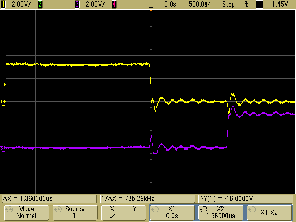
I attached a screenshot from the oscilloscope to show an issue.
The yellow line is an input signal (GPIOA[23], falling edge) and the purple line is the response via GPIOA[22]. A delay between input signal and response is 1.36 uS (!!!) that means I can’t service interrupts fater than 700 kHz which sound ridiculous for the CPU with 700 MHz clock.
There are my functions:
void prvGpioISR(void)
{
	static const uint32_t base_addr = XGPIO + GPIO_SIZE * PORT_A;  //GPIOA base address
	static uint8_t pingpong = 1;  // ping-pong flag
	mmio_write_32(base_addr + GPIO_PORTA_EOI, 0xFFFFFFFF);	// Clear interrupt flag
	writePin(PORT_A, 22, pingpong);  // Toggle output pin every interrupt
	pingpong ^= 1;
}

void writePin( uint8_t port, uint8_t pin, uint8_t value )
{
	uint32_t base_addr = XGPIO + GPIO_SIZE * port; // GPIO base address
	uint32_t val = mmio_read_32( base_addr + GPIO_SWPORTA_DR);
	val = (value == GPIO_HIGH ? ( val | BIT(pin) ) : ( val & (~BIT(pin))));
	mmio_write_32(base_addr + GPIO_SWPORTA_DR, val);
}
Could anyone tell me how to decrease latency? What the reason for it?
2 Likes
Could you also share how you setup your ISR?
Sure.
// Initial function
void main_cvirtos(void)
{
	// Start the tasks
	request_irq(MBOX_INT_C906_2ND, prvQueueISR, 0, "mailbox", (void *)0);
	request_irq(GPIO0_INTR_FLAG, prvGpioISR, 0, "gpio", (void *)0);

	main_create_tasks();
	vTaskStartScheduler();
}

// Gpio task function
void prvGpioIntTask(void *pvParameters)
{
	(void)pvParameters;	// Ignore parameters

	pinMode(PORT_A, 23, GPIO_INPUT);  // Input pin
	pinMode(PORT_A, 22, GPIO_OUTPUT);	// Pin for DEBUG purpose
	configureInterruptPin(PORT_A, 23, GPIO_INT_FALLING);
	...
}

// Function configure pin as interrupt source
void configureInterruptPin(uint8_t port, uint8_t pin, uint8_t intMode)
{
	uint32_t base_addr = XGPIO + GPIO_SIZE * port;
	// Set interrupt by edge
	mmio_clrsetbits_32(base_addr + GPIO_INTTYPE_LEVEL, 0, BIT(pin));
	if(intMode)
		// Rising edge
		mmio_clrsetbits_32(base_addr + GPIO_INT_POLARITY, 0, BIT(pin));
	else
		// Falling edge
		mmio_clrsetbits_32(base_addr + GPIO_INT_POLARITY, BIT(pin), 0);
	// Set debounce = ON
	//mmio_clrsetbits_32(base_addr + GPIO_DEBOUNCE, 0, BIT(pin));
	// Clear pending interrupts
	mmio_write_32(base_addr + GPIO_PORTA_EOI, 0xFFFFFFFF);
	// Enable inerrupt for selected pin
	mmio_clrsetbits_32(base_addr + GPIO_INTEN, 0, BIT(pin));
}

// Function configure mode of pin (input or output)
void pinMode( uint8_t port, uint8_t pin, uint8_t value )
{
	mmio_clrsetbits_32(
		XGPIO + GPIO_SIZE * port + GPIO_SWPORTA_DDR,
		BIT( pin ),					// CLEAR mask
		value ? BIT( pin ) : 0		// SET mask
	);
}