It’s a bit confusing: on one hand, the datasheet mentions somewhat 1.8V. On the other hand, people are connecting i2c, spi, uart devices to the board without any issues. Besides, there are teeny-tiny smd components (0102?) which could easily be resistor dividers, but, probably, they are just for certain pins? I am a bit afraid of breaking my board)
1 Like
here it says:
The logic level of
GP26andGP27pins is 1.8V, and the logic level of other GPIO pins is 3.3V logic level.
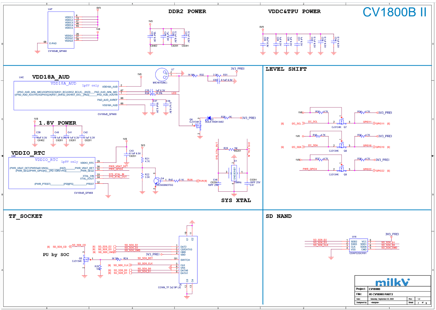
but I don’t see that many level shifters in the schematics…
The SG2002 datasheet is scary). AFAIR there are several ‘power domains’ and it seems, depending on which domain the pin is connected (through registers?), the logic level can be different.
1 Like