Where is wiringX source used in duo-sdk? I need to modify it

All,

Where are the sources used to build the wiringX library used by the duo-sdk. The current sdk only includes a wiringx.h header and a shared library duo-sdk/rootfs/usr/lib/wiringx.so. Further, there is no source provided in the buildroot as it includes the compiled shared-object library, e.g. /buildroot-2021.05/package/wiringx/src/libwiringx.so

This is not the general version of wiringX on github or the radxa variant because it includes the following functions not included in either of the other repositories:

int wiringXSetPWMPeriod(int pin, long period);
int wiringXSetPWMDuty(int pin, long duty_cycle);
int wiringXSetPWMPolarity(int pin, int polarity);
int wiringXPWMEnable(int pin, int enable);

I need the actual source so I can add a routine to read a set number of bytes from an I2C address on the Inversense MPU9250. Currently the wiringx library included in the sdk only provides:

int wiringXI2CReadReg8(int fd, int reg);
int wiringXI2CReadReg16(int fd, int reg);

This does not accommodate reading an arbitrary number of bytes from device register such as the 7, 8 or 512 bytes of data needed to read the linear and angular acceleration with/without the temperature or reading from the MPU FIFO. I need to be able to specify a wiringXI2CReadReg(int fd, int reg, uint8_t *buf, int length); to accommodate the chip without having to loop providing an offset - which would be awkward at best, unreliable at the other end of the scale.

In fact, all that really needs to be done is to expose the wiringX i2c_smbus_access() function that is wrapped within the wiringXI2CReadReg8() and wiringXI2CReadReg16() functions that are available. The wiringX source already contains:

extern inline __s32 i2c_smbus_access(int fd, char rw, int cmd, int size, union i2c_smbus_data *data);

It appears simply exposing the i2c_smbus_access() woulds expose a read/write with the size parameter allowing a single read of the 512 byte FIFO instead of having to make 512 calls to wiringXI2CReadReg8() which would destroy the efficiency of the read.

Where is the source for /buildroot-2021.05/package/wiringx/src/libwiringx.so so I can modify and build that along with the image?
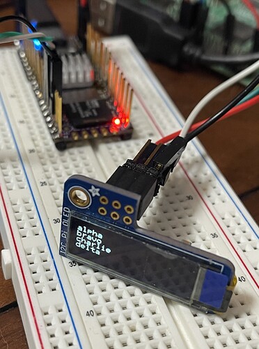
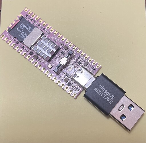
Rather than worrying about the wiringX library at all, it was simple to use the busybox miscutils/i2c_tools.c implementation of i2c_smbus_access() along with i2c_smbus_read_i2c_block_data() and i2c_smbus_write_i2c_block_data() for all I2C communications with the chip. This correctly handles 1, 2 or multiple byte read/write without calling different functions.

For those facing the same need of being able to read and write varying number of bytes from and to the i2c bus, the following works fine for 1-byte to a max of 32 (max allowed by standard). Simply use wiringX to initialize itself and the the i2c address to obtain the file descriptor to /dev/i2c-X and than just use the following i2c_read_reg() or i2c_write_reg() for all reads and writes to the i2c bus.

Also, for chips with multiple i2c bus address addresses (e.g. the mpu9250 with one i2c address for the accelerometer/gyro registers and then another i2c address for the magnetormeter chip and its registers), just use the same /dev/i2c-X wtih the secondary bus address, e.g. wiringXI2CSetup ("/dev/i2c-X", AK8963_ADDRESS) to obtain a new file descriptor in order to access the second chip and its set of registers (like opening a file in two different modes resulting in two different file descriptors accessing the same file).

/**
 * i2c_smbus_xxx function taken from busybox 1.36.1 miscutils/i2c_tools.c.
 * https://elixir.bootlin.com/busybox/latest/source/miscutils/i2c_tools.c
 */

/**
 *  I2C helper function providing ioctl call for both
 *  i2c_smbus_read_i2c_block_data and i2c_smbus_write_i2c_block_data.
 *
 */
static int32_t i2c_smbus_access (int fd, char read_write, uint8_t cmd,
				 int size, union i2c_smbus_data *data)
{
  struct i2c_smbus_ioctl_data args;

  args.read_write = read_write;
  args.command = cmd;
  args.size = size;
  args.data = data;

  return ioctl (fd, I2C_SMBUS, &args);
}


/**
 * I2C read length (len) bytes from I2C device configured with open
 * file-descriptor (fd) from device register (reg) address into
 * the storage pointed to by data.
 */
int32_t i2c_read_reg (int fd, uint8_t cmd, uint8_t *vals, uint8_t len)
{
  union i2c_smbus_data data;
  int i, err;

  if (len > I2C_SMBUS_BLOCK_MAX) {
    len = I2C_SMBUS_BLOCK_MAX;
  }
  data.block[0] = len;

  err = i2c_smbus_access (fd, I2C_SMBUS_READ, cmd,
                          len == 32 ? I2C_SMBUS_I2C_BLOCK_BROKEN :
                                      I2C_SMBUS_I2C_BLOCK_DATA, &data);
  if (err < 0) {
    return err;
  }

  for (i = 1; i <= data.block[0]; i++) {
    *vals++ = data.block[i];
  }
  return data.block[0];
}


/**
 * I2C write length (len) bytes from I2C device configured with open
 * file-descriptor (fd) from device register (reg) address into
 * the storage pointed to by data.
 */
int32_t i2c_write_reg (int fd, uint8_t cmd, const uint8_t *vals, uint8_t len)
{
  int err;
  union i2c_smbus_data data;

  if (len > I2C_SMBUS_BLOCK_MAX) {
    len = I2C_SMBUS_BLOCK_MAX;
  }
  
  for (int i = 0; i < len; i++) {
    data.block[i+1] = vals[i];
  }
  data.block[0] = length;

  err = i2c_smbus_access (fd, I2C_SMBUS_WRITE, cmd,
                          I2C_SMBUS_I2C_BLOCK_BROKEN, &data);
  
  if (err < 0) {
    return err;
  }
  
  return data.block[0];
}
1 Like

I located a wiringX branch for the Milk-V Duo
git clone --branch milkv-duo GitHub - willian-milk/wiringX: Modular GPIO interface

1 Like

Thank you! Your search-foo is much stronger than mine. I looked for that thing, but could not pin it down.

Wait - thatā€™s not the wiringX branch used for Milkv-Duo, itā€™s header is missing:

int wiringXSetPWMPeriod(int pin, long period);
int wiringXSetPWMDuty(int pin, long duty_cycle);
int wiringXSetPWMPolarity(int pin, int polarity);
int wiringXPWMEnable(int pin, int enable);

Please let me know if you get your code working with this branch of wiringX.

I tried the blink.c example with some success as the print statements will display but the led does not blinkā€¦

I updated my reply. This isnā€™t the version of wiringX provided by the duo-sdk. No PWM functionality. Also, Iā€™ve gotten away from using wiringX. With no source, itā€™s hard to modify as needed. Iā€™ve just gone to using the ioctl() call. (which is what wiringX does behind the scenes). It takes a bit longer, but at least all the needed source files are provided as part of the kernel code.

Niceā€¦
I will give that code a look.
Thanks

To initialize an I2C device without wiringX just using ioctl() and i2c-smbus you can do:

/**
 * i2c_init_device opens the i2c sysfs device (e.g. "/dev/i2c-0") and
 * verifies it can communicate with the i2c address for the device.
 *
 * \return returns open i2c file descriptor for device on success
 * -1 otherwise.
 */
int i2c_init_device (const char *i2cdev, uint16_t addr)
{
  int fd;

  if ((fd = open (i2cdev, O_RDWR)) < 0) {
    return -1;
  }

  if (ioctl (fd, I2C_SLAVE, addr) < 0) {
    return -1;
  }

  return fd;
}

The additional header files to include if you go this route are (at minimum, just for the init and I2C read/write functions) are:

#include <sys/ioctl.h>
#include <sys/types.h>
#include <sys/stat.h>
#include <fcntl.h>

#include <linux/types.h>
#include <linux/i2c.h>
#include <linux/i2c-dev.h>

You can look at the wiringX source for the read/write functions (byte, word, etc.). They are fairly straight-forward to implement. Basically read/write byte and read/write word are special cases of the read/write multiple byte functions where you specify the size of the data being written or read. For OLED use, you can get away with just using the read/write byte function. But for other devices like MPU9250 IMU, etcā€¦ you need to ability to read and write multiple bytes at a time.

Good luck with your coding!

Are you working with the Duo 64M or the Duo 256M ?

I see a similar wiringX gripe from kkkkk

Could you recommend an SPI function I could try on the 1.5ā€ OLED display?

Thank you

I have a 64M duo. Just running the default image. Iā€™m using I2C for the OLED display (thatā€™s how my tiny .96" SSD1306 displays are wired). You can use wiringX for either SPI or I2C for the OLED. They work fine with the write_byte functions. It is the MPU where I need to read/write 14 bytes at a time where wiringX doesnā€™t help.

There are a number of good SSD libraries on github. Just choose the language you use. I would recommend C, but many are in C++ ā€“ which is fine. I have had no problems building in the duo-sdk.

Awesome!
I found SSD1306 Linux on GitHub
Itā€™s working great

Thank you again!!

Great job. I just cannibalized the C++ SSD1306 OLED Library for Raspberry Pi and removed the broadcom backend and replaced it with the i2c-smbus/ioctl backend so it works both on the Pi and Duo now.

As you did, on my 2nd Duo, I used double-length header-pins so I can still use the GPIO pins on top when I snap the duo into the USB / Ethernet IOB. When you set a fixed MAC and uncomment hostname in /etc/dhcpcd.conf, your Dou then functions like any other computer on your network and allows whatever you use for network dhcp and DNS to provide an IP and name resolution. (I have a server that runs ICS dhcpd and DNS that allows dhcpd to provide dynamic updates to the DNS server that keeps everything straight)

The duo is a cool piece of hardware. Good luck with your coding!

Nice work!
Do you post your edits to a GitHub repo ?

Just received a few Duo256m boards from Arace.tech. Fast turnaround time to the USA.

AliExpress just cancelled my Duo256 order so Iā€™m glad Arace came through.

I did notice the Duo256 has GP13 AUX0 and GP12 AUX1 functions.
Not sure what they are used for yet.

My Duo farm is expanding fastā€¦ would like to find a PoE HAT or some way of powering them off a PoE switch.

Regards

I have a few Duoā€™s setup with the RJ45 modules.

They work wellā€¦ I just donā€™t like that the SD card butts up to the pins.

If you donā€™t have oneā€¦
I highly recommend getting a USB-C power meter. It works great IMO

That is a cool setup. Iā€™d never heard of a USB-C power-meter ā€“ but Iā€™ll get one. I didnā€™t think about the RJ-45 solder pins butting up to the SD card. Thatā€™s something Iā€™ll have to watch for if I put the connector on the end of my other duo.

I do have a github account drankinatty, but I havenā€™t put the SSD1306 lib over there yet. I have a local git repo for it while Iā€™m figuring out the best way to go. Currently I need to split the i2c-smbus code out into a separate shared-object library, so multiple projects can use it without conflicting headers.

Iā€™ll let you know when I push the repo to github.

Sorry for interrupting your conversation, but it seems you are experienced guys in designing linux drivers :wink: I was following this tutorial:

and I am getting an error in this line:
if(gpio_request(4, ā€œrpi-gpio-4ā€)) {
(line 136)
For starters, I was trying to build a driver for my LED (RTCSYS_GPIO, pin2 in my case). Is it because the pin ā€˜is occupiedā€™ by the original driver and i have to somehow ā€˜freeā€™ it up? (which doesnā€™t seem right to me, but i still leave such a possibility), or, which seems more probable, because of the defines mess? Which parameters should I pass when calling gpio_request?

That looks like a very good tutorial. While it is difficult to draw much information from the code you have posted, I suspect there is a mix-up on which GPIO-group your pin actually belongs to. The Pinout Diagram is very differently ordered from the actual gpio innerworking of the duo. You need to start with the Duo Schematic v1.2.pdf.

There are four GPIO Pin groups GPIO, GPIOA, GPIOC and Pwr GPIO. The group numbers matter. The define which base pin in the system corresponds to any given GPIO. For example: here are the base pins for the various groups:

 (group)             (base pin in group)
 Pwr GPIO            352
 GPIO3 (D)           384
 GPIO2 (C)           416
 GPIO1 (B)           448
 GPIO0 (A)           480

It is critical you know which pin and which group you are talking about. This number are completely different from the GP0, GP1, ā€¦ you find on the dou pinout. So if what you are calling GPIO4 (shown as GP4) is the 5th GPIO (6th pin) down from the top ā€“ that corresponds to GPIO19 which has the name Pwr GPIO19 and since the Pwr Group Base Pin is 352, then the GPIO number for your pin is 352 + 19 = 371. (confusing as hell until you make friends with which group has which pin, etcā€¦ A handy cheatsheet I came up with is:

See duo-schematic-v1.2.pdf (page 1 for cross-reference below)

GPIO from the shell (sorted by /sys/class/gpio/gpioN number):

GP0-GP22               (hardware
pinout                1-20, 21-40)
GP pin  GPIO name 	GPIO pin 	GPIO number 	Notes
 14     GPIOA14           19              494
 15     GPIOA15           20              495
 12     GPIOA16           16              496
 13     GPIOA17           17              497
 18     GPIOA22           24              502
 16     GPIOA23           21              503
 17     GPIOA24           22              504
 19     GPIOA25           25              505
 21     GPIOA26           27              506
 20     GPIOA27           26              507
  0     GPIOA28           1               508
  1     GPIOA29           2               509
 10     GPIOC9            14              425     1.8V
 11     GPIOC10           15              426     1.8V
 22     PWR_GPIO4         29              356     1.8V
  9     PWR_GPIO18        12              370
  4     PWR_GPIO19        6               371
  5     PWR_GPIO20        7               372
  8     PWR_GPIO21        11              373
  7     PWR_GPIO22        10              374
  6     PWR_GPIO23        9               375
  3     PWR_GPIO25        5               377
  2     PWR_GPIO26        4               378

Sorted by reguar pinout GPx Pin:

GP0-GP22               (hardware
pinout                1-20, 21-40)
GP pin  GPIO name 	GPIO pin 	GPIO number 	Notes
  0     GPIOA28           1               508
  1     GPIOA29           2               509
  2     PWR_GPIO26        4               378
  3     PWR_GPIO25        5               377
  4     PWR_GPIO19        6               371
  5     PWR_GPIO20        7               372
  6     PWR_GPIO23        9               375
  7     PWR_GPIO22        10              374
  8     PWR_GPIO21        11              373
  9     PWR_GPIO18        12              370
 10     GPIOC9            14              425     1.8V
 11     GPIOC10           15              426     1.8V
 12     GPIOA16           16              496
 13     GPIOA17           17              497
 14     GPIOA14           19              494
 15     GPIOA15           20              495
 16     GPIOA23           21              503
 17     GPIOA24           22              504
 18     GPIOA22           24              502
 19     GPIOA25           25              505
 20     GPIOA27           26              507
 21     GPIOA26           27              506
 22     PWR_GPIO4         29              356     1.8V

Itā€™s enough to make your head spin. But the bottom line is you have to know what actual pin and pin number you need to use ā€“ then things just work. Buy Aspirin there will be a few headaches along the way :p.

See if you can come up with a correct wiring config based on the pin data and give the tutorial another go.

2 Likes

Hi Red
I will check out the RPi4 tutorial

Sounds like the kernel module will monitor one of the Duo GPIO pins to switch on pin 25 LED ?

Regards

Going back to the MPU9250ā€¦
Iā€™m interested in getting a breakout board.
I found a few boards listed on google.
Would you recommend a specific board ?

Regards